
Disassembly
1. Remove the rear cover bolts and remove the rear cover.
2. Remove the tail light switch, gasket and mounting bracket.
3. Remove poppet valve plugs, valve springs and balls.
4. Remove the speedometer drive gear assembly.
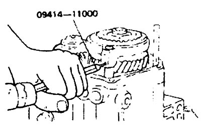
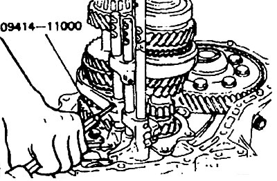
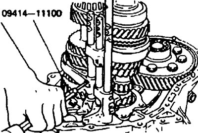
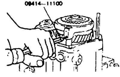
5. Remove the spring font using a special tool (09414-11000).
6. Remove shaft nuts.
- 1) Turn away nuts of a leading and intermediate shaft.
- 2) Shift the transmission into reverse using the control lever and selector lever.
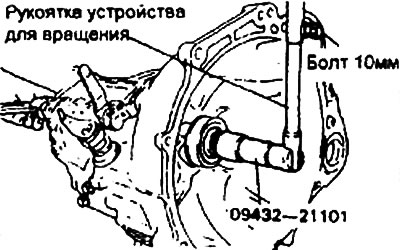
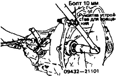
- 3) Install special tool (09432-21101) to the drive shaft.
- 4) Screw a 10 mm bolt into the hole on the clutch housing and attach the handle to the special tool.
- 5) Remove the nut using the bolt as a stop.
7. Remove the fifth gear synchronizer bushing and shift fork.
8. Remove the fifth gear synchronizer hub, synchronizer ring, fifth gear and needle bearing.
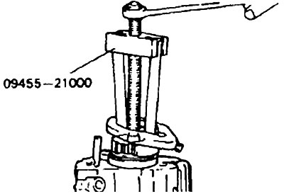
9. Remove the idle gear using the special tool (09455-21000).
10. Remove the reverse gear shaft bolt and stop ball assembly.
11. Remove cover and transaxle housing bolts.
12. Remove the differential oil seal and oil guide.
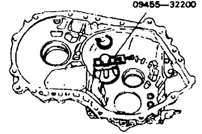
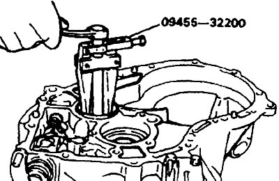
13. Remove the output shaft bearing outer race and spacer ring using the special tool (09455-32200).
14. Remove the intermediate shaft bearing outer race and spacer ring.
15. Remove the differential bearing outer race and spacer ring.
16. Remove the reverse shift lever and reverse shift shoe.
17. Remove the reverse gear shaft and remove this wheel.
18. Remove the spring pins using the special tool (09414-11000).
19. Disconnect the shift guide and fork assembly.
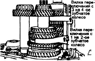
- 1) Switch the shift fork from the first to the second gear to the second gear.
- 2) Switch the shift fork from the third to the fourth wheel.
- 3) Remove the switch guide assembly.
20. Remove the bearing holder.
21. Lift the driveshaft assembly and remove the intermediate shaft assembly.
22. Remove the output shaft assembly and differential gear assembly.
23. Remove the input shaft bearing outer race and spacer ring using the special tool (09455-32200).
24. Remove the output shaft bearing outer race and spacer ring using the same special tool (09455-3220)
25. Remove the differential bearing oil seal.
26. Remove the input shaft oil seal.
Installation.
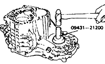
1. Install the input shaft oil seal using the special tool (09431-21200).

2. Install the driveshaft seal using the special tool (09431-21000).
3. Install the differential gear bearing spacer.
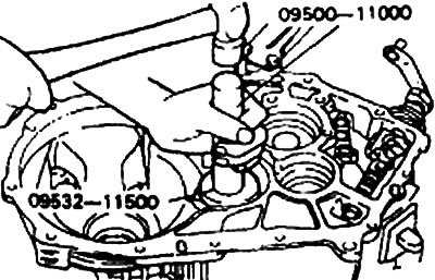
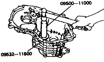
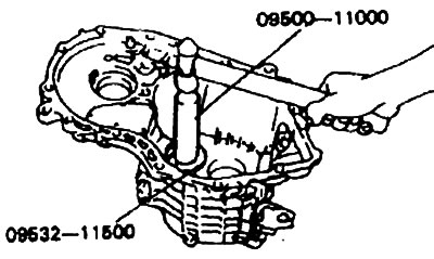
4. Install the output shaft bearing outer race and spacer ring using the special tool (09500-11000, 09532-11500).
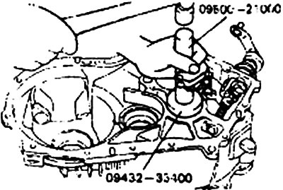
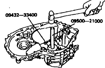
5. Install the oil guide and the intermediate shaft bearing outer race and spacer ring using the special tool (09500-21000, 09432-33400).
6. Install the differential gear assembly and output shaft assembly.
7. When lifting the input shaft assembly, install the intermediate shaft assembly at the same time.
8. Install the bearing holder.
9. Assemble the switch guide assembly:
- 1) Install the 1st to 2nd shift bushing.
- 2) Install the 3rd to 4th shift bushing.
- 3) Install the 1st to 2nd shift guide assembly and the shift fork assembly with the selector lever pulled toward the 5th reverse shift guide side.
- 4) Install the 3rd-4th/5th-reverse shift guide assembly and shift forks with the selector lever fully pressed against the side of the 1st-2nd guide.
- 5) Install the 3rd to 4th shift guide/reverse assembly and shift fork assembly.
10. Assemble the spring pin.
- 1) Install the spring pins with the special tool (09414-11100).
- 2) When installing, make sure that the slot of the spring pin aligns with the center line of the guide.
Warning. Do not reuse used spring pins.
11. Install the reverse gear lever assembly.
12. Install the reverse gear shaft and the wheel itself in the direction shown in the figure.
13. Install the reverse switch lever and block.
14. Install the intermediate shaft bearing outer race and spacer ring into the transmission case using the special tool (09500-21060, 09432-33400).
15. Install the output shaft bearing outer race and spacer against the transmission case using the special tool (09500-11000, 09532-11500).
16. Install the differential bearing spacer in the transmission case.
17. Install the input shaft oil seal in the transmission case using the special tool (09431-21200).
18. Assemble spacer ring (for axial runout control).
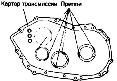
- 1) Place two pieces of solder approximately 10 mm long and 3 mm in diameter on the bearing outer race as shown in the illustration and install the outer race.
- 2) Install the transmission case and tighten the bolts to the correct torque.
- 3) Remove the transmission case.
- 4) Remove outer ring and solder.
- 5) Measure the thickness of the crushed solder with a micrometer, and select and install a spacer ring with a thickness that provides the standard amount of axial runout.
Standard value:
- Axial runout of intermediate shaft: 0.05-0.10 mm
- Axial runout of output shaft: 0.05-0.10mm
- Axial runout of differential housing: 0.05-0.10 mm
19. Install the oil guide on the transmission case.
20. Apply recommended sealing compound to transmission case joint (1-2 mm).
- Recommended sealant: Tri Bond 1216
21. Install the transmission housing by bolting it to the clutch housing.
22. Install the restrictor ball and gasket.
23. Center the shaft with a Phillips screwdriver.
24. Tighten the idler reversing gear shaft bolt to the specified torque.
25. Install balls, springs and valve plugs.
26. Install the rear light assembly.
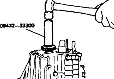
27. Install the idle gear using the special tool (09432-33300).
28. Install the fifth gear, synchronizer ring, needle bearing, and synchronizer hub.
29. Install the fifth gear shift fork and the synchronizer sleeve at the same time.
30. When installing the spring pin, use the special tool (09414-11100).
31. Make sure that the slot of the spring pin is in line with the center line of the guide.
Warning. Do not use reused spring pins.
32. Assemble the lock nuts.
- 1) Install special tool (09432-21101) to the drive shaft.
- 2) screw in the bolt (diameter 10 mm) into the hole in the surface of the clutch housing and attach the handle to the special tool (09432-21101).
- 3) Shift the transmission into reverse using the control lever and selector lever.
- 4) Tighten the nut to the required torque.
33. Apply sealant (1-2 mm) back cover and replace it.
- Recommended composition: Three Bond 1216
34. Install the tail light switch, gasket and mounting bracket.
35. Install the gear assembly to drive the speedometer.